-

Solar inverter DC end short circuit
One of the most common, yet overlooked, threats to PV performance is DC insulation short circuits. These faults can lead to power generation losses, expensive repairs, and even fire hazards. In this article, we'll dive into the causes, risks, and solutions available to combat. . If you've ever faced a sudden blackout or noticed smoke near your electrical setup, chances are, you've encountered an inverter short circuit. provides characteristic. . This piece separates myths from reality, adds credible data, and gives you practical steps to reduce short-circuit risk while improving overcurrent protection. Traditional synchronous generators can source many times their rated current during a fault. In solar PV systems, short circuits can happen due to: Line-to-Line Fault: Occurs when two conductors of different phases or the same phase come. . X”d, X'd, Xd, X2 are only meaningful for a single inverter operating point and one single fault location! Danger! : Underestimation of fault current contribution is possible with Thevenin representation when impedance is not changed to adapt to fault location 1.
[PDF Version]
-
Solar inverter motherboard circuit explanation
A typical circuit board architecture includes the following key subsystems: DC input interface and EMI filter module, DC-DC boost converter (for non-microinverter systems), DC-AC inverter bridge, MPPT control module, gate drive circuit, voltage/current sensing network . . A typical circuit board architecture includes the following key subsystems: DC input interface and EMI filter module, DC-DC boost converter (for non-microinverter systems), DC-AC inverter bridge, MPPT control module, gate drive circuit, voltage/current sensing network . . This comprehensive technical article dives deep into the engineering essentials of solar inverter circuit board design, offering a detailed exploration for electrical engineers and hardware designers. It covers the fundamental architecture and topology analysis, delves into the critical circuit. . A solar inverter circuit diagram is a graphical representation of the electronic components and their connections used in a solar power inverter. A solar power inverter is an essential part of a solar power system as it converts the direct current (DC) generated by solar panels into alternating. . When a DC to AC inverter is operated through a solar panel, it is called a solar inverter. Please be aware that the various appliances or electronics in your home run on AC, not DC.
[PDF Version]
-
Principle of solar inverter Sampling Circuit
The Fig-1 shows the solar inverter circuit diagram. Solar panel converts the light energy into dc electrical energy and then the dc electric energy is. . The invention provides an AC current filtering and sampling circuit of a photovoltaic inverter. The current conversion sampling circuit. . A solar inverter performs the essential function of converting direct current (DC) from photovoltaic (PV) panels into alternating current (AC) suitable for grid connection or local loads. Different types of inverters are shown in Figure 11. High-efficiency, low THD. .
[PDF Version]
-

Simplified diagram of the working principle of solar inverter
Understanding the block diagram helps grasp the working principle and functionality of a solar inverter. It plays a vital role in harnessing. . By the end of this comprehensive guide, you'll understand exactly how solar inverters solve this critical conversion challenge, backed by real testing data and expert insights from our extensive field experience with over 500 residential solar panel installations and commercial installations. It is a vital component in a solar power system, responsible for converting and monitoring the power generated by the solar array. The method by which dc. . So, in this tutorial, we will make the “PV Solar Inverter Circuit diagram. Please be aware that the various appliances or electronics in your home run on AC, not DC. The inverter is a kind of oscillator. It can produce a high-power AC output from a DC supply. Can we make it? Is it difficult? Is it expensive? Too many Question! This is beginning for learning how the inverter works.
[PDF Version]
-
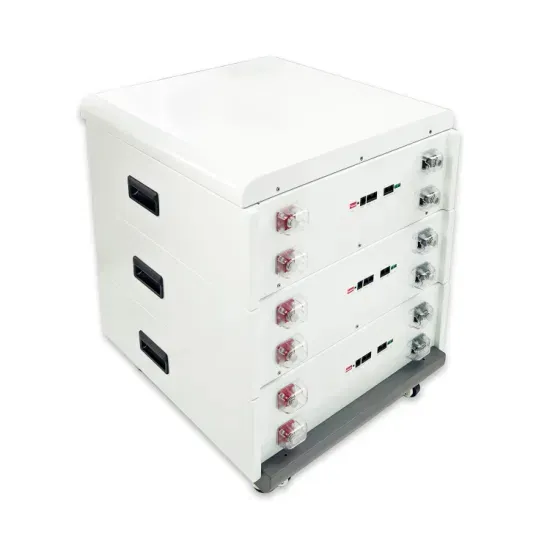
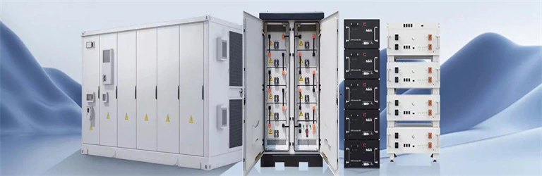
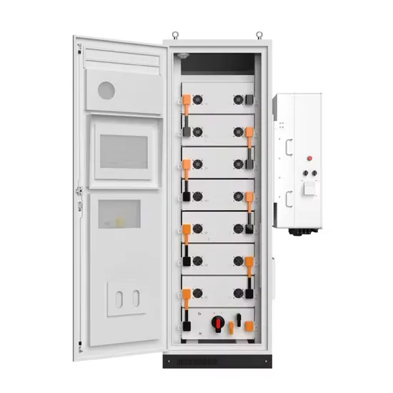
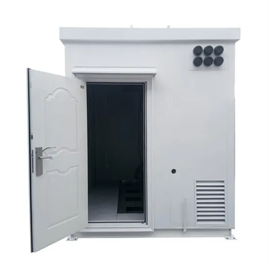
High-temperature resistant inverter cabinets for mountainous areas
AZE's HVAC outdoor telecom enclosures and cabinets are designed specifically to protect high density installations of network equipment in outdoor environments and are ideal for wireless, wireline, and utility and applications. . In high-temperature scenarios such as desert solar power plants, smelter workshops, and tropical coastal industrial zones (where ambient temperatures often exceed 40°C), the stable operation of electrical control cabinets faces severe challenges. Trusted by telecom operators for reliable climate-regulated outdoor protection. Designed for harsh environments and seamless integration, this IP54-rated solution features a 105KW bi-directional PCS, optional air- or liquid-cooled thermal. . ETA Enclosures USA provides electrical enclosures designed for renewable energy applications, including solar power inverters, wind turbine control systems, and battery storage solutions. Our enclosures protect critical energy infrastructure from environmental hazards while ensuring compliance with. . Our 200KWh outdoor cabinet energy storage system works with PowerNet outdoor control inverter cabinets for modular expansion. This means you can meet the needs of large-scale applications without limitations, such as powering communities or supporting commercial projects. It can meet the capacity requirements. .
[PDF Version]