-
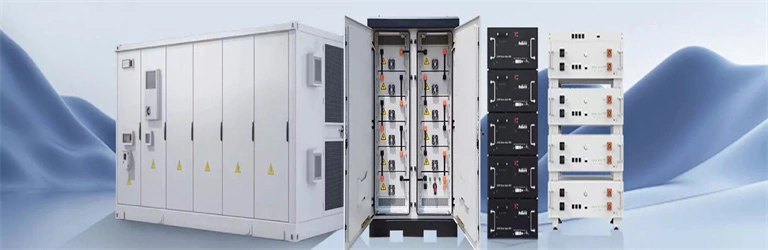
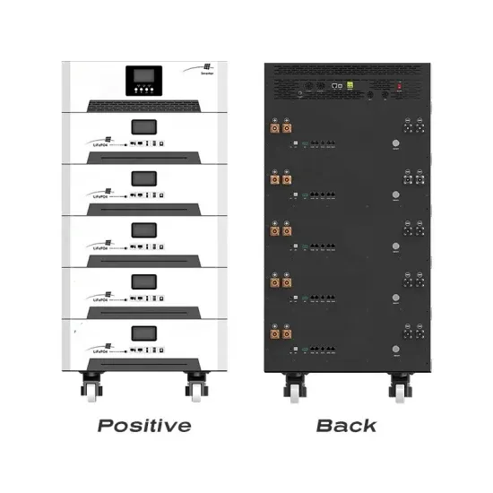
Energy storage system cae effect diagram
A CAE effect diagram is essentially a digital crystal ball showing how your energy storage system will behave under specific conditions. Think of it as: Don't just take my word for it. [1] The first utility-scale CAES project was in the Huntorf power plant in Elsfleth, Germany. . In 2024, CAE (Computer-Aided Engineering) has become the Swiss Army knife for designing battery systems that don't just work, but survive real-world punishmen Picture this: engineers at Tesla's Gigafactory staring at glowing CAE effect diagrams like ancient sailors reading star charts. These. . In compressed air energy storages (CAES), electricity is used to compress air to high pressure and store it in a cavern or pressure vessel. Compared with traditional industrial compressors, the compressor of CAES has higher off-design. . CAES works in the process: the ambient air is compressed via compressors into one or more storage reservoir (s) during the periods of low electricity demand (off-peak) and the energy is stored in the form of high pressure compressed air in the reservoir (s); during the periods of high electricity. . compressed air energy storage systems.
[PDF Version]
-
Simple diagram of solar panels
The diagram highlights a typical grid-tied system, showing a simple, step-by-step flow from sunlight to power and the path electricity takes—from panels on the roof to outlets in your home. Solar panels on your roof capture sunlight. It's great to have visual representations to help us to understand how scientific processes work. Below we will take a look at multiple solar system diagrams for off-grid use in a vehicle or remote location and a home grid-tied system.
[PDF Version]
-
570W photovoltaic panel size diagram
We have an image for Jinko Solar Co Ltd JKM570N-72HL4 - See below for a reference of what this panel may look like (can differ depending on date and manufacturer). Discover why this solar module has become a favorite in. . Half-cell and multi-main gate design with ultra-thin dielectric film to isolate metal and semiconductor can achieve carrier tunneling efect to ensure carrier conduction and increase power output. * Please refer to Suntech Standard Module Installation Manual for details. Less partial shading current mismatch loss so more power output. Better. . I ZY570MIONH-1441 570 Watts Efficient photovo- Itaic modules 12 years product warranty Made years IQENEPV Mono-crystalline Solar PV Modules Dimensions of PV Module(mm): Dimensions: Weight: 2278M 134*35mm 28. 0 Electrical characteristics: Current-Voltage Characteristic(l-V Curve) PV module: Renepv. . Example: 5kW solar system is comprised of 50 100-watt solar panels. Can you put a 5kW solar system on your roof? For that, you will need to know what size is a typical 100-watt solar panel, right? To bridge that gap of very useful knowledge needed. . Leader of high efficiency solar modules. Full-automatic facility and industry-leading technology Best-in-class durability and reliability *The specification and key features described in this datasheet may deviate slightly and are not guaranteed. Due to ongoing innovation, R&D enhancement, Loom. .
[PDF Version]
-
Photovoltaic panel grounding wire size standard diagram
This guide breaks down how to read a PV system grounding diagram in under 10 minutes. Whether you're reviewing a plan set or prepping for an AHJ inspection, these tips will help you avoid costly mistakes. Article 690 of the NEC mandates that #8 AWG or #6 AWG are the smallest wires that can be used with grid tied solar panels and inverter systems, and for solar panel output circuits, #10 or #12 AWG are allowed. A ground rod is also. . vary, but generally follows a standard pattern. It specifies the mi imum size of grounding conductors (more on this later). 47 always be read in conjunction with section 240 of the NEC. 83 meters) apart and must not be less than 2.
[PDF Version]
-
Photovoltaic panel battery connection diagram
In this article, I will explain how to connect a solar panel to a battery step-by-step. I will also share a few tips you need to know along the way. Here is a diagram connecting a single 100W solar panel to a 12V 100Ah lithium battery and a 500W inverter:. This comprehensive guide will walk you through the exact steps to safely connect solar panels to battery systems, covering everything from essential equipment selection to advanced troubleshooting techniques. Use the red wire to match the charge. . Two parallel strings of two modules in series. For example, a 100W solar panel can make (under standard test conditions, STC) 18 volts (V) and 5.
[PDF Version]